My notes from Chapter 3 of “An Introduction to the Mechanics of Solids” by Crandall and Dahl.
-
Summary of Chapter 2, “Introduction to Mechanics of Deformable Bodies” (according to 3.1)
Analysis of Deformable Bodies
- Study of forces and equilibrium requirements
- Study of deformation and conditions of geometric fit
- Application of force-deformation relations
-
What is Chapter 3, “Forces and Moments Transmitted by Slender Members” all about?
We are going to be concerned with the study of forces and the equilibrium requirements, as applied to slender members.
-
What are Slender Members?
Those members of engineering structures whose lengths are much longer as compared to either of their cross-sectional dimensions are called slender members. In case of loops, the diameter must be much larger than the thickness of the long rod that is looped.
-
What is the subscript notation we are using to denote forces and moments at a section in slender members?
We usually have two letters in the subscript.
For a force , denotes the direction of the vector perpendicular to the area of cross-section in consideration and, denotes the direction of the Force.
Thus, is an axial force while and are shear forces.
Similarly, for a moment , has the same meaning as above and is the direction of the force that is responsible for this moment.
Hence, is a twisting moment while and are bending moments.
-
What about the sign convention?
A positive force or moment on a positive face is positive. So is a negative force or moment on a negative face (implied by Newton’s third law). Here, positive and negative mean in a positive or negative coordinate direction respectively.
-
What problem solving approach do we usually follow, when we have multiple loads on a slender member?
The Method of Sections
- First, draw a free body diagram of the entire slender member and mark all the forces acting on it.
- Then, use the equations of equilibrium and to get relations between them.
- Finally, cut the member at a section of your choice and repeat step 2 on either of the resulting segments.
-
What is a shear force diagram?
A graph of shear force on a body versus the distance along a beam (from a given point) where it acts.
-
What is a bending moment diagram?
A graph of bending moment on a body versus the distance along a beam (from a given point) where it acts.
-
Why do we need these diagrams?
If we wanted to design a durable engineering structure, we would need to know the maximum forces that can act on the members of the structure. Further, knowing the force distribution may allow us to better arrange all the different members in the structure together. I’ve not personally designed any such structures but in my opinion, a well engineered structure is one which is easy to put together and take apart, kind of like Legos.
-
What is the Point of Contraflexure?
It is the point on a bending moment diagram where the bending moment changes its sign (i.e. positive to negative or vice versa). At this point the value of the bending moment is zero.
-
What is Intensity of Loading?
Intensity of loading, is defined as the limit,
It’s dimensions are force per unit Length.
-
How do we approach problems that have distributed loading conditions?
-
Calculating the Resultant Force
One method is to calculate the resultant force on the slender member.
where is the intensity of loading - a function of , the distance from an end of the member.
These can be obtained by writing the force and moment balance equations twice - once with and and then with the RHS of the above equations - and comparing them.
The line of action of the resultant force passes through the centroid.
The formulae for forces acting in two and three dimensions are also similar.
-
Using Differential Equilibrium Relationships
Consider a very small element of the given slender member, analyse the shear forces and bending moments acting on it and then limit the small segment of length / area / volume to zero. This will give us differential equations that we can integrate to find relationships between forces. Use boundary conditions to find out the values of constants of integration.
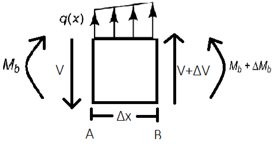
Also,
In both the above equations, limiting we get,
-
-
What is the relationship between the shear force, bending moment and loading diagrams?
- The slope of the bending moment curve is the negative ordinate of the shear force curve.
- The slope of the shear force curve is the negative ordinate of the intensity of loading curve.
-
How do we approach problems that have distributed loading conditions but only in some segments, or with different magnitudes?
Use the method of sections along with either of the two methods above or, use Singularity Functions.
-
What are Singularity Functions?
Singularity functions are defined as,
They have the following property,
There are two exceptions:
and are zero everywhere except at where they are infinite.
-
What do singularity functions represent?
-
represents a unit concentrated moment.
-
represents a unit concentrated load. This is also known as the Dirac Delta function in physics.
-
represents a unit step.
-
represents a unit ramp.
-
represents a unit parabolic curve.
-
-
If there are no distributed loads present, where does the maximum bending moment occur?
It always occurs at a loading point.
-
Why?
When all forces lie in the same plane, the bending moment diagram consists only of straight line segments. And even when they don’t, the bending moment diagram consists only of concave outward curves.
-